Part 10: Sailing Physics Simulation
Some issues with animations when using the Bevy game engine have led me to introduce a home baked physics engine, more advanced sailing simulation, and unfortunately a long overdue update of Pirate Sea Jam.
Scraping third party physics engines
As mentioned in previous posts, I've tested the physics engines Bevy Rapier and Bevy XPBD for the project, but decided against including them in the game for a few reasons.
Besides some issues I had with the XPBD physics engine, I was afraid that complex physics calculations would become indeterministic across different platforms and make fast paced online multiplayer gaming harder to implement. These, not necessarily underpinned, assumptions lead me to remove any external physics library and go for something more plain sailing, so to speak.
Simplifying the simulation
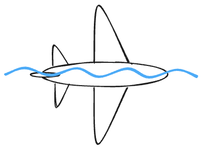
Instead of simulating buoyancy forces, angular inertia and what not, I ended up with the ship just sitting on top of the animated ocean, aligned according to the tangent plane of the wave at the current position of the ship.

The tangent plane to a surface at a given point is the plane that "just touches" the surface at that point.
The orientation and position of the ship now became a straight forward calculation, depending only on a few simple parameters.
- The shape of the wave as a function of elapsed time
- The virtual position of the ship in the horisontal XY plane
- The current yaw rotation of the ship.
Finally the speed of the vessel was constant and not affected by any wind direction.
This configuration is probably as simple as it gets with the smallest risk of introducing floating point rounding errors and issues in online gaming scenarios.
The animation problem
Let me get back to the animation problem mentioned above. I had issues with playing out multiple animations within the same object hierarchy, which eventually made me leave the path of computational simplicity and an arcade style approach to game mechanics, in favor of a detour to the land of great complexity and sailing physics simulations. (Watch out for a future post , me writing about going back to a simpler and more predictable setup, hehe.)
I wanted to have two co-existing animations, each one targeting a different part of the ship's 3D model. Firstly, I animated the cannons aiming up and down when pressing the fire key and then the squash n' stretch of the barrels as a cannon ball is shot off. Secondly, I wanted to target the whole ship, which was supposed to rock back and forth as the cannons were fired to give the impression of recoil. But downhearted by the error message
Animation player on 36v0 has a conflicting animation player on an ancestor. Cannot safely animate.
I decided that I would rock the boat by applying forces and using physics simulations, rather than just applying a swaying animation.
Reintroduce a physics engine, you say?
–Yes indeed! I decided to add back physics simulations, but this time I was going to build it myself from scratch and make the art of captaining be a result of somewhat realistic sailing physics. With the help of the excellent book "Game Physics Engine Development" by Ian Millington, I dove deep into the laws of motion for rigid bodies, aerodynamics, and other concepts needed to write my own physics engine.
Aerodynamics
Ships are able to sail faster than the wind speed and it's possible to sail up against the wind to a certain degree. But what laws does actually govern these motions and how do you model them in a video game?
The theory behind wings, sails and keels (what is commonly known as airfoils), share many similarities, including the central concepts of lift and drag.
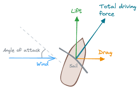
Acting forces
The two main driving forces for any airfoil are lift and drag. Looking at a sailing ship top down (or an airplane from the side), the lift force is directed perpendicular to the wind and drag force is directed along with the wind. The magnitude of these forces depend on sail or wing characteristics and the angle of attack between the airfoil and the wind.
Below the water line the keel and rudder act in a similar but opposing fashion. The boat is not just pushed straight forward, it also has a tendency to slip sideways due to the forces of the wind. The flow of water on the keel and the rudder come into play here and create forces that resists the leeway drift and act in a stabilizing manner.
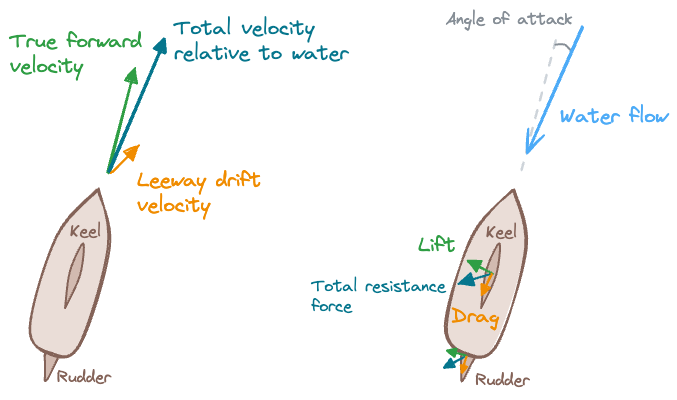
The leeway drift is working in the same direction as the driving force, but is normally just a fraction of the driving force. Opposite to the relative velocity we have the water flow force that generate drag and lift on the keel and rudder.
Note that if the driving force and the leeway drift increases, so will the resistance forces from the keel and rudder do, giving us a self stabilizing system.
So how are the forces actually calculated?
The direction of the lift and drag forces are always the same in relation to the wind or water flow, but the strength of those forces vary. As the angle of attack between the wind and sail or water flow and keel change, the magnitude of the lift and drag forces will also change.
The result can be plotted on a graph with the force coefficient as part of the force magnitude on the Y axis and the angle of attack on the X axis.
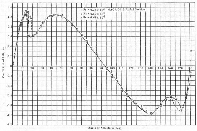
Looking at the graph above we see a sudden dip in the curve as the angle of attack increases beyond a certain critical point, which depicts something called stalling. A stall occurs when the airflow is not traveling streamlined along the airfoil but separates from the surface due to an increased angle of attack (typically around 15 degrees).

Stall hinders the ability of airfoils to produce lift. As the stall increases, lift is only generated in the reduced region of the wing where the air flow is not separated. Consequently the airfoil is dominated by drag during stall.
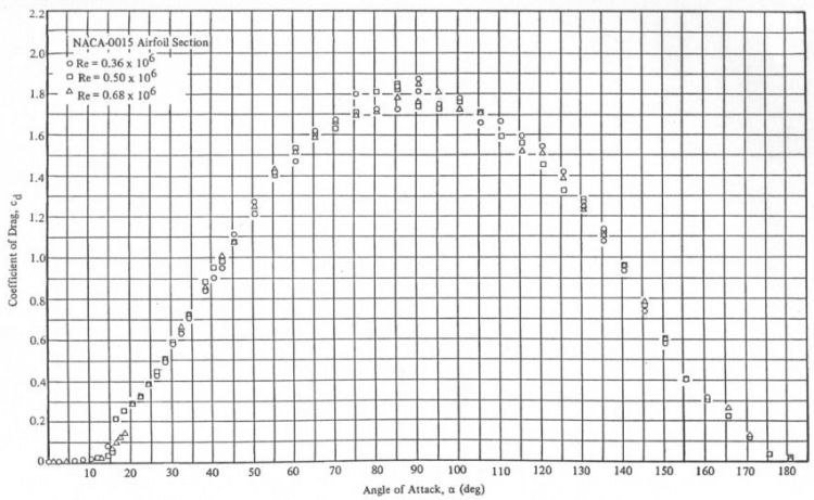
The graph for the drag force shows a peak at 90 degrees and the graph which corresponds to the wind blowing straight into an airfoil and dragging the vessel forward. At this point the airfoil is not producing any lift.
In reality there are no simple equations to calculate the lift and drag based on angle of attack. The characteristics of the airfoil and the relationship between lift, drag, and angle of attack is complex and typically determined experimentally in wind tunnels. The result can then be plotted in graphs as shown above.
Keeping it simple
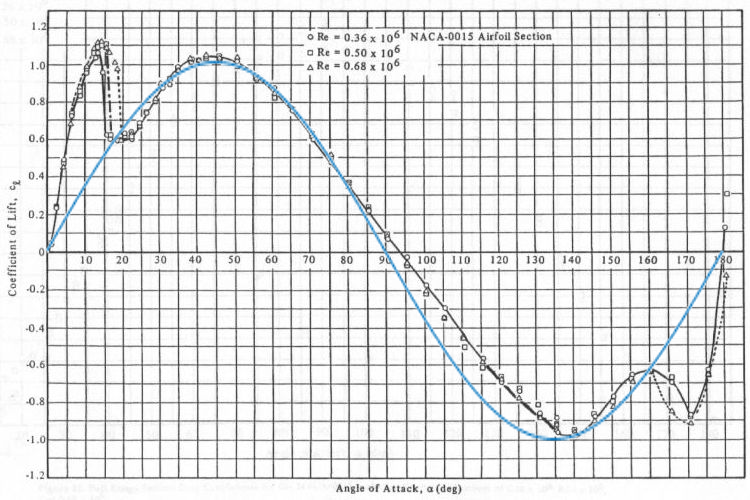
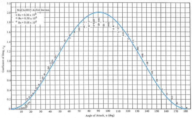
If we are willing to make significant simplifications, ignoring the stall regime and consider the airfoils to be symmetrical (which would be more true for a keel than for a sail or a wing) we can define lift and drag as functions of the angle of attack in the following concise ways.
Lift_coefficient = sin(2 × angle_of_attack)
Drag_coefficient = 1 - cos(2 × angle_of_attack)
The trigonometric graphs have been superimposed on the original plots to demonstrate the resemblance between real measured values and an simplified symmetric airfoil.
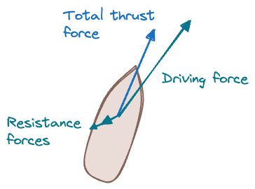
Putting it all together
Let's look at how to calculate the numerical values of the lift and drag forces. These two forces are proportional to something called dynamic pressure (the air density times velocity squared divided by two), as well as the area of the airfoil, and one of the characteristic coefficients.
Dynamic_pressure = 1/2 × air_density × velocity^2
Lift_force = dynamic_pressure × airfoil_area × lift_coefficient
Drag_force = dynamic_pressure × airfoil_area × drag_coefficient
The sail orientation and the direction of the wind would typically be known at all times, but to calculate the angle of attack between the two can be a bit tricky.
Calculating the angle of attack
Assuming we know the normal vector of the airfoil surface (that is the arrow perpendicular to the surface) and the wind direction vector, how do we calculate the angle of attack (which we in turn need to calculate the lift and drag coefficients as seen above)?
When looking at the schematic diagram below we see that the angle of attack is periodical over 180 degrees when the sail rotates a full 360 degrees.
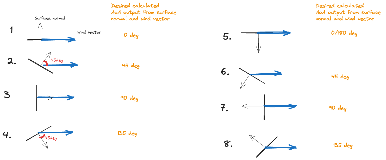
We will use the normal vector of length one or its opposite counterpart depending on which one is pointing roughly in the same direction as the wind. In mathematical terms we pick the normal vector or the opposite normal vector depending on which one has a positive dot product with the wind vector. (Check one of the previous posts for a brief overview of the concept of "dot product".)
This means that we can easily change examples 6, 7, and 8 in the diagram to examples 2, 3, and 4 respectively.
Finally we use the inverse trigonometric function arcsin and the dot product again to grab the angle of attack in one fell swoop. The angle of attack will be equal to arcsin of the dot product of the wind vector and the normal vector, divided by the length of the wind vector.
Angle_of_attack = arcsin(wind_vector ⋅ normal_or_opposite_normal_vector / wind_vector_length)
We would normally use the trigonometrical counterpart arccos to calculate an angle between two vectors like this, but since we want the angle of attack to be zero when the wind is perpendicular to the normal vector arcsin is suitable in this situation.
This is an extreme simplification but works pretty well when we don't require a high fidelity simulation. There are other, perhaps more concise, approaches to finding the combined lift and drag forces, which include mathematical objects called tensors, more specifically a three by three matrix, but covering that would have to be a future post.
But the ship is not moving... or?
One very evident problem with Pirate Sea Jam at the moment is that a player gets the impression that the pirate ship is standing still even though it is actually sailing using all tricks of the trade.
This is because we miss points of references!
First of all the waves currently propagate from all directions and the ship is centered on the screen. To make things worse all the vertices that form the waves are more or less stationary in relation to the ship, just swaying back and forth and up and down as the waves come rolling. (Check out a previous post for details about ocean tiles being fixed to the ship to create an illusion of infinite ocean.)
Next up
A visually better solution would be to have the vertices stationary in relation to the world coordinates so that the ship moves across the vertices and triangles that form the sea.
Last but not least, a nice addition would be to have some sort of foam trace behind the ship as it sails forward to emphasize the motion of the pirate sloop.
Watch out for coming updates. Until then – Ship ahoy!
Leave a comment
Log in with itch.io to leave a comment.